Water for Injection is the utility plant engineers lose sleep over. Generation gets attention, but storage, distribution, and sampling can introduce significant risks even when generation performs correctly. A well-sized skid can still deliver marginal water at the point of use if tank, loop, and fittings lack equal discipline. This guide summarizes practical best practices for plant engineers, validation specialists, and procurement teams.
Why Storage and Distribution Carry Most of the Risk
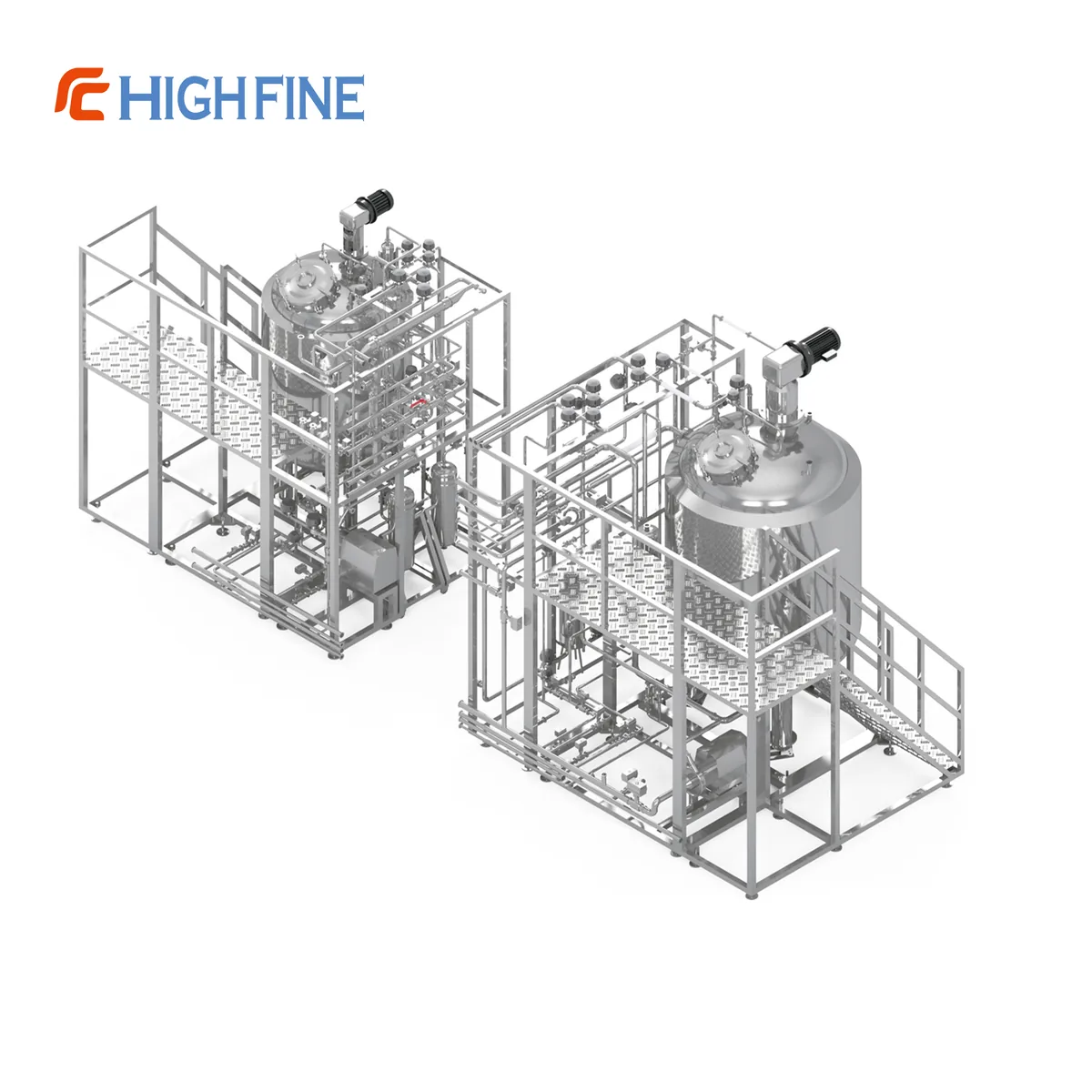
Once WFI leaves generation, it is a warm, nutrient-poor but not nutrient-free liquid in contact with stainless steel, gaskets, diaphragms, and valves. Every meter adds surface area; every low point, dead branch, and horizontal run adds a place where flow slows, biofilm can establish, and temperature can stratify. Every joint is a potential rouging site or crevice that resists cleaning. USP, EP, and JP expectations are demanding because the route is parenteral. Conductivity, total organic carbon, microbial limits, and bacterial endotoxin must be met at the point of use, not only at the still outlet. The loop must prevent recontamination and demonstrate continuous control. Consensus design is a closed, continuously circulating loop with no stagnant branches, matched to a justified storage temperature, sanitization, and monitoring strategy.
Hot Storage Above 80 °C Versus Ambient Storage With Ozone
Two mainstream philosophies dominate, and both are defensible when executed properly.
Hot storage above 80 °C suppresses microbial proliferation, so the loop is hostile to bioburden even where flow is intermittent. Many organizations use it as default for high-risk products because control is passive: no ozone generator, UV lamp, or chemical addition. Trade-offs include insulation throughout, point-of-use heat exchangers to cool water for sampling or processing, expansion and support attention, personnel protection, and continuous energy use. Hot water also accelerates some corrosion and rouging, so passivation and weld integrity matter. Heat exchangers must be designed and validated as part of the loop, including pressure drop, cleanability, and drainability.
Ambient storage with ozone uses ozone generated on site and injected into the circulating stream, typically with UV destruction ahead of points of use and catalytic destruction on tank venting and overflow. Advantages are lower energy use, no burn hazard, and easier sampling without cooling. Ozone can support microbial control in contacted water and wetted surfaces; headspace and upper-surface sanitization require a separately demonstrated coverage strategy. Trade-offs are operational complexity: concentration must be measured and controlled; sensors need calibration; the destruct system must be verified so no ozone reaches product; and materials and elastomers must tolerate oxidation. Ambient loops demand rigorous monitoring because loss of ozone generation is a silent loss of primary control.
Neither option is universally correct. The choice turns on product portfolio, utilities, operator skill, and validation philosophy. Some sites use hot WFI loops and ambient ozonated purified water loops; others standardize on hot WFI to simplify training and SOPs. The selected regime must be justified in validation documentation, continuously monitored, and supported by circulation and sanitization design.
Continuous Turbulent Circulation
A WFI loop should circulate continuously, including nights, weekends, and shutdown periods, except when isolated for maintenance under a documented procedure. Circulation supports temperature uniformity and reduces stagnation; microbial control also depends on hygienic design, sanitization, and monitoring. Flow should be turbulent throughout, including the return leg and sections closest to the tank. Evaluate Reynolds number at minimum permitted circulation and the operating and draw-off conditions that produce the lowest flow in each critical section. Return flow to the tank is standard instrumentation and should be alarmed, trended, and reviewed as part of batch or utility release. Variable-speed pumping is common; flow must remain turbulent at the minimum speed the control system permits. Set that minimum deliberately, document the rationale, and verify it during qualification.
Dead Legs, Slope, and Drainability
A dead leg is any branch or extension off the main flow path where water can stagnate. Industry expresses acceptability as length-to-diameter ratio, L/D. The widely applied expectation is that dead legs be as short as practicable, and older FDA inspection guidance cited six pipe diameters; current ASME BPE practice recommends 2:1 or less, and most new designs target that. Many organizations write a stricter internal requirement, and a stricter internal requirement is rarely criticized. Practical implementation matters: use block-and-bleed arrangements, diaphragm valves with the shortest spool pieces, zero-static-tee or weir-type bodies where appropriate, and instrument tees oriented in the flow path. Each point of use, instrument, drain, and sample valve is a dead-leg candidate and should be reviewed on the isometric.
A loop that cannot be fully drained cannot be confidently sanitized, inspected, or repaired. Piping should slope continuously back to a low-point drain, with no undulating runs, sagging supports, or horizontal sections relying on velocity alone to empty. Slope should be shown on isometrics and verified in the field. Every drain should be at a genuine low point and sized for the required drain-down time. Tank bottoms should be fully drainable, coned or dished appropriately, with the outlet positioned so the last liter leaves the vessel. Valves should drain. Transfer lines and heat exchangers should be evaluated individually; horizontal shell-and-tube units are a classic drainability problem.
Vent Filters, Spray Balls, and Tank Details
The tank must breathe as level and temperature change, and that air must not carry contamination into the headspace. Hydrophobic vent filters are standard, arranged to be steam-sterilizable or otherwise sanitizable, and installed so condensate does not blind the membrane or create a wet path for microbes. Redundant or duplex housings allow integrity testing and replacement without breaking the tank's protected state. The housing should drain, and the vent line should not create an un-sloped pocket. Filter integrity should be testable in place, and the method should be documented in qualification.
The tank interior above the water line must be cleaned and sanitized. A spray ball or set of spray devices distributes cleaning and sanitizing fluid across headspace, roof, and upper wall. Coverage should be verified, not assumed; riboflavin testing under UV light remains the most common practical method. Spray device selection should account for available flow and pressure, tank geometry, and sensitivity of internal components such as baffles or dip tubes. An undersized spray ball can produce a clean ring and an uncleaned dome. Tanks should be closed, pressure-rated for hot-water or steam sanitization, fitted with a rupture disc or pressure-relief device rated for the sanitization condition, and equipped with hygienic, drainable level instrumentation. Headspace must permit proper venting. Insulation should be continuous on a hot loop, with no thermal bridges at supports and nozzles.
Sampling Point Placement and Temperature Mapping
Sampling points should represent the worst case, not the most convenient case. The return line to the tank is standard for routine monitoring because it represents water that has traversed the entire loop. Points of use that are furthest from the tank, least frequently used, or at the end of the longest branches should be included on a rotating basis. Use hygienic sampling arrangements and include samples representative of actual production draw-off; define flushing and handling according to the monitoring objective. Flush volume, duration, valve opening technique, and order of sampling should be specified and followed consistently; trend comparison over months is meaningful only if the method is stable.
For hot loops, temperature mapping demonstrates that the entire loop, including return, tank, and least-favored sections, stays above the specified storage temperature under defined conditions. Mapping should use calibrated data loggers at enough locations to characterize the system, and should be repeated or supplemented after significant changes to insulation, flow, heat exchangers, or setpoints. Mapping is most informative under worst-case conditions: lowest circulation flow, lowest ambient temperature, and a representative draw-off pattern. Cold spots are usually found where insulation is interrupted, at heat exchangers, and at the far end of the loop.
Routine Monitoring: Conductivity, TOC, Endotoxin, Microbial
A credible program combines online instrumentation with periodic laboratory testing.
- Conductivity is measured online at the return to the tank and compared with applicable USP, EP, or JP limits, with alarm and action levels below the compendial limit.
- Total organic carbon is measured online or by grab sample with validated laboratory methods and trended with conductivity.
- Microbial enumeration uses samples from the return line and selected points of use, with methods suitable for the water type and validated for the matrix.
- Bacterial endotoxin is tested at a frequency consistent with product risk and demonstrated system performance, against the WFI monograph limit.
Trending matters more than pass/fail judgment. A conductivity reading that rises steadily but stays within limits is worth investigating. A microbial count that shifts from a stable baseline is a signal even if low. Review trends on a defined cadence, document the review, and link deviations to investigation and corrective action.
Sanitization Cycles and Documentation
Sanitization can use hot water, steam, or chemical agents depending on loop design. Hot-water sanitization leaves no residue and reaches surfaces chemicals may not wet reliably, but the entire loop, including dead-leg-free branches, sample valves, and vent lines, must achieve the target condition. Cycle validation should include temperature distribution, duration above target, and evidence that every part of the loop was included. Documentation is the other half: a written procedure, a record of parameters achieved, and a review step confirming completion before the loop returns to service. Changes to duration, setpoint, flow, or coverage alter a validated state and should be assessed accordingly.
What Auditors Actually Check
Auditors focus on high-yield design and documentation questions. They frequently ask for the P&ID and isometrics and trace dead legs with a scale; undocumented short branches are a common finding. They may ask for slope verification records, the drain-down procedure, and observation of a drain point. Spray coverage evidence, usually riboflavin test reports for the tank and, where applicable, piping, is commonly requested. Vent filter integrity and replacement records should include method, acceptance criteria, and history. Temperature records and mapping reports should link mapping locations to alarm setpoints. Trend review evidence should prove someone reviewed data and acted. Sampling procedures and training records matter because sampling errors are a frequent root cause of inconsistent results. Sound design and traceable documentation support inspection readiness; findings also depend on actual qualification, operation, monitoring, and investigation practices.
Where HIGHFINE Fits: WFI Generation Equipment
Founded in 1992 and based at No. 379 Zhonghua East Road, Haimen City, Jiangsu Province, China, HIGHFINE PHARMATECH CO., LTD. — a Sino-foreign joint venture, as described on the company website — manufactures pharmaceutical water equipment. The company supplies the generation end of the WFI chain: multi-effect distillers (B, F and S series; the S series uses 316L stainless steel with a 0.6 µm Ra finish) and vapor-compression distillers producing WFI at 0.05 µS/cm, according to the company website. The F series includes FAT validation, and the S series ships with full validation documentation. Certificates available upon request. The company's equipment is exported to markets across South East Asia, the Middle East, Africa, Europe, and the Americas, as stated on the company website.
FAQ
Should a WFI loop be stored hot or at ambient with ozone?
Both are accepted. Hot storage above 80 °C provides passive microbial control and is simpler to operate; ambient ozonated storage uses less energy and simplifies sampling. The choice should be justified in validation documentation and supported by monitoring that detects loss of control in either regime.
What is the acceptable dead-leg limit for WFI?
Older guidance cited a length-to-diameter ratio of six or less; current ASME BPE practice recommends 2:1 or less, and most new designs target that. Many organizations write a stricter internal standard. Whatever limit is adopted, it should be applied consistently, verifiable from isometrics, and applied to every branch, instrument tee, drain, and sample valve.
How often should a WFI loop be sanitized?
There is no universal frequency. The interval should be established during qualification, supported by microbial and endotoxin trend data, and revisited when data change. Auditors expect a documented rationale, a validated cycle, and records showing each cycle was completed and reviewed.
Can a WFI loop be stopped during plant shutdowns?
Continuous circulation is preferred, but controlled shutdowns are common. If a loop is stopped, a procedure should cover draining or isolation, sanitization before restart, and any additional monitoring or testing required to return the loop to service. The validated state should be re-established and documented, not assumed.
Where should routine samples be taken?
The return to the storage tank is standard because it represents water that has passed through the entire loop. Points of use, especially least-frequently used and most remote, should be included on a rotating schedule. Dedicated sample valves, consistent flush procedures, and documented technique are essential for comparable data over time.
How do we move from design to a validated loop?
Start with a clear user requirement specification, then align storage regime, circulation design, dead-leg and drainability criteria, instrumentation, and sanitization strategy before fabrication. Factory acceptance testing and a complete validation documentation package allow design intent to be traced through installation and qualification.
Talk to a Water System Engineer
Talk to a Water System Engineer
Start the conversation
Talk to a Water System Engineer
30+ years of pharma water projects. No sales script.